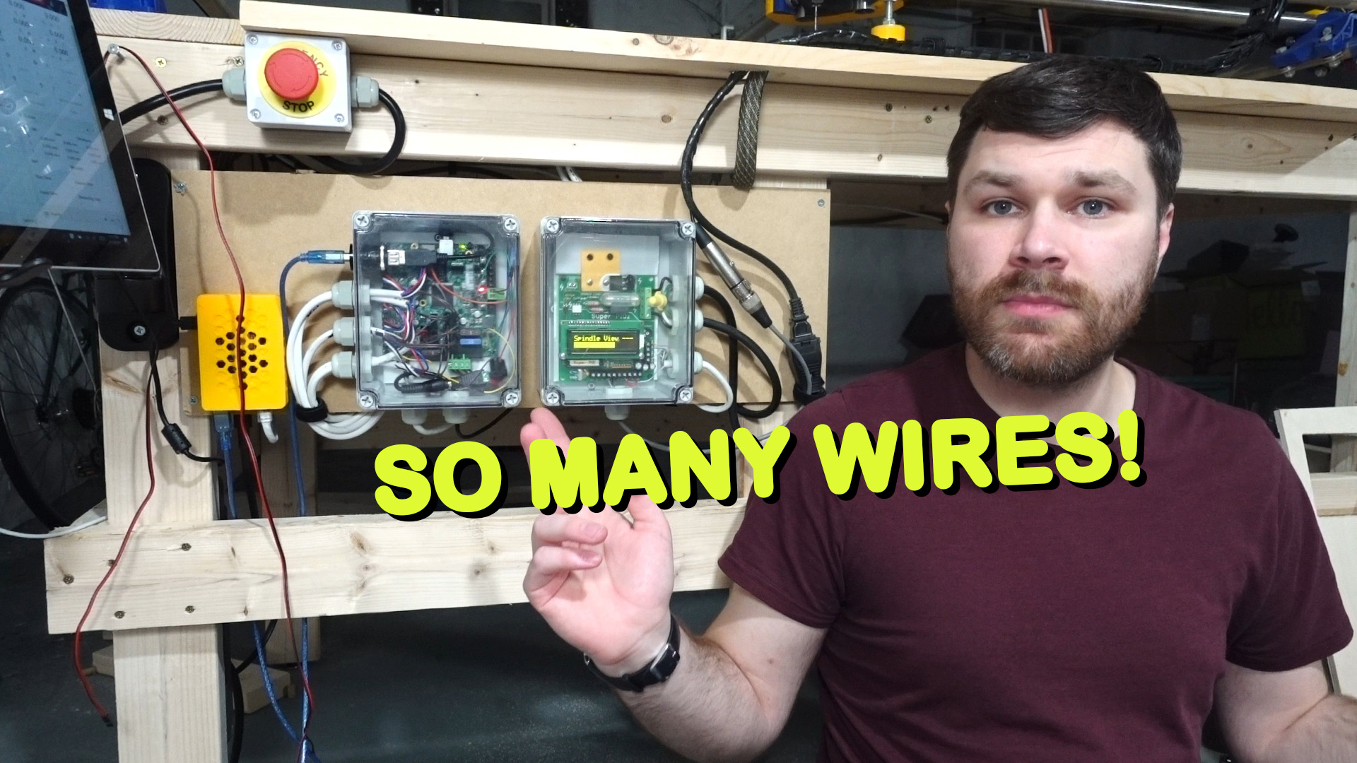
What a post title! I could probably have made it longer too. Anyway, I wanted to share all of my notes on configuring the Archim2 controller with the Marlin firmware. The MPCNC we are building has dual endstops. We also splurged and bought a SuperPID to allow speed control of the router. The SuperPID isn’t necessary for a successful CNC router but we were willing to spend a little extra for that flexibility.
SuperPID Mounting and Testing
The setup of the SuperPID with the router was fairly easy. It took a some time to determine where to mount the sensor on the spindle. I settled for cutting a little notch out inside the body of the router which gave clear access for the sensor to be mounted. Then I used a little white paint to mark half of the circumference of the spindle and dry tested the sensor and it was reading properly! I glued everything in and tested again and thankfully it all still worked. Once the glue dried I was able to run the motor and I now have precise control over the motor speed. Exciting!
Archim2 to SuperPID Wiring
As I was getting ready to configure and upload the Marlin firmware (Link to the V1Engineering preconfigured versions) I discovered that there wasn’t a lot of documentation for properly configuring the SuperPID. I started with the V1CNC_Archim2_Dual-2.0.7.2 version of the firmware (You’ll want to check if a newer version is available). I spent a bunch of time adjusting various configuration settings to finally get the spindle control to work properly. At first I couldn’t get anything to work right. Switching the router on and off was easy but the PWM speed control was just all over the place. I had to take a step back and actually look at the wiring between the Archim2 and SuperPID first.
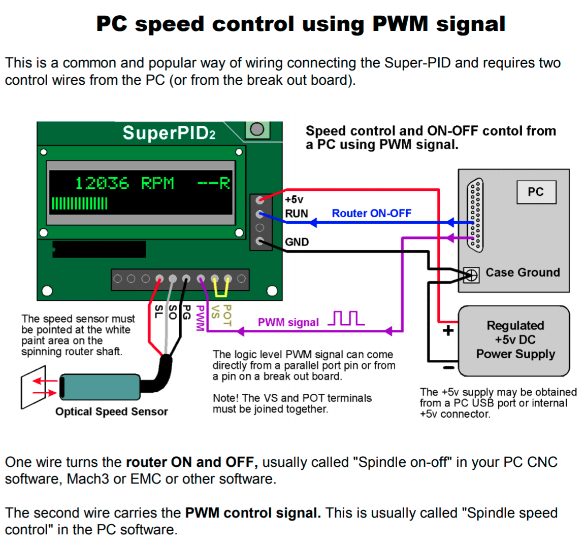
As noted in the SuperPID V2 instructions, you need 2 wires to control the on/off and PWM:
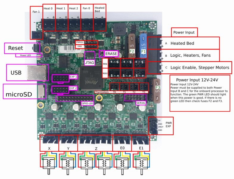
Finding an unused digital IO port for the spindle on/off control on the Archim2 board was fairly easy after looking at the schematic (I used J20 PB15). I had a much harder time finding a free hardware PWM pin for the speed control. I wanted to use a normal GPIO pin from the J20 header. But after some tests, and reading online I discovered that the only accessible hardware PWM pins you can use on the Archim2 are the Fan and heat ports at the top of the board. These pins will work except they are driven at 12v instead of 5v. That is a problem because the SuperPID expects 5v PWM. So now I’ve got my PWM pin but its the wrong voltage.

Source
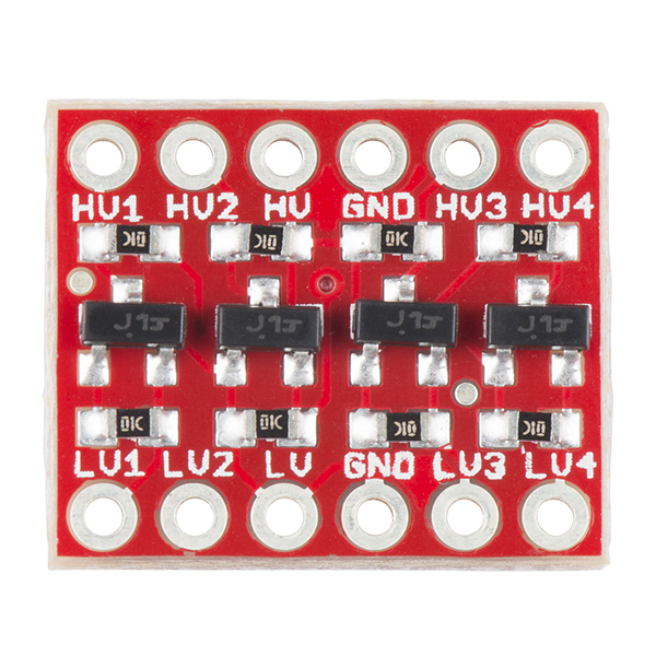
I ended up using this logic level converter from Sparkfun to convert the logic PWM signal from the 12v fan output to 5v that the SuperPID can accept. I used the port labeled Fan0 in the image above but referenced as Fan1 / Pin 4 within the Marlin firmware. The positive pin on the fan port goes to the HV pin on the Sparkfun board. The negative pin goes to HV1. Only one of the ground pins need to be connected on the Sparkfun board and I used a ground pin from P1 (just below the fan port). I grabbed a 5v pin from J12 (EXP1 in the image above) on the Archim2 and connected it to LV. LV1 then goes to the PWM pin on the SuperPID board.
Marlin Firmware Configuration
Now I’ve got my pins figured out and they are all at the correct voltage. Let’s then look at the configuration of the Marlin firmware. First up is to configure the pins for the spindle control. For the Archim2, the pins file is located at Marlin/src/pins/sam/pins_ARCHIM2.h inside the Marlin firmware directory.
First off, not sure if it is necessary but I commented out the fan pin definition.
//#ifndef FAN_PIN
//  #define FAN_PIN                              4  // D4 PC26 FET_PWM1
//#endif
#define FAN1_PIN                               5  // D5 PC25 FET_PWM2
Next, at the end of the file we define the spindle enable and PWM pins
#define SPINDLE_LASER_ENA_PIN  GPIO_PB15_J20_15  // digital pin
#define SPINDLE_LASER_PWM_PIN  4      // digital pin - MUST BE HARDWARE PWM
Now that the pins are defined we’ll head over to the Configuration_adv.h file to set the spindle settings. The biggest note here is that the SPINDLE_LASER_PWM_INVERT needs to be set to true. Before I changed this to true I was getting really confusing reactions when testing out the pwm speed control from the Archim2. Once I set this to invert the PWM signal I was getting much more predictable results.
The last thing I will note about the speed control is about the CUTTER_POWER_UNIT. I really wanted to be able to set the speed through gcode as RPM. But I was never able to get an accurate matchup between the requested RPM and actual RPM on the SuperPID. I’m not sure what was causing the discrepancy. I tried adjusting all of the other options but could never get the RPM to match at all. I gave up and kept CUTTER_POWER_UNIT as PWM255 and will have to use 0-255 for setting the speed value. At the end of the day it’s not a huge deal. I’ll just have to do some tests and write down what values equal certain RPM.
/**
 * Spindle & Laser control
 *
 * Add the M3, M4, and M5 commands to turn the spindle/laser on and off, and
 * to set spindle speed, spindle direction, and laser power.
 *
 * SuperPid is a router/spindle speed controller used in the CNC milling community.
 * Marlin can be used to turn the spindle on and off. It can also be used to set
 * the spindle speed from 5,000 to 30,000 RPM.
 *
 * You'll need to select a pin for the ON/OFF function and optionally choose a 0-5V
 * hardware PWM pin for the speed control and a pin for the rotation direction.
 *
 * See https://marlinfw.org/docs/configuration/laser_spindle.html for more config details.
 */
#define SPINDLE_FEATURE
//#define LASER_FEATURE
#if EITHER(SPINDLE_FEATURE, LASER_FEATURE)
  #define SPINDLE_LASER_ACTIVE_STATE    LOW    // Set to "HIGH" if the on/off function is active HIGH
  #define SPINDLE_LASER_PWM             true   // Set to "true" if your controller supports setting the speed/power
  #define SPINDLE_LASER_PWM_INVERT      true  // Set to "true" if the speed/power goes up when you want it to go slower

  //#define SPINDLE_LASER_FREQUENCY       2500   // (Hz) Spindle/laser frequency (only on supported HALs: AVR and LPC)

  /**
   * Speed / Power can be set ('M3 S') and displayed in terms of:
   *  - PWM255  (S0 - S255)
   *  - PERCENT (S0 - S100)
   *  - RPM     (S0 - S50000)  Best for use with a spindle
   */
  #define CUTTER_POWER_UNIT PWM255

  /**
   * Relative Cutter Power
   * Normally, 'M3 O<power>' sets
   * OCR power is relative to the range SPEED_POWER_MIN...SPEED_POWER_MAX.
   * so input powers of 0...255 correspond to SPEED_POWER_MIN...SPEED_POWER_MAX
   * instead of normal range (0 to SPEED_POWER_MAX).
   * Best used with (e.g.) SuperPID router controller: S0 = 5,000 RPM and S255 = 30,000 RPM
   */
  //#define CUTTER_POWER_RELATIVE              // Set speed proportional to [SPEED_POWER_MIN...SPEED_POWER_MAX]

  #if ENABLED(SPINDLE_FEATURE)
    //#define SPINDLE_CHANGE_DIR               // Enable if your spindle controller can change spindle direction
    #define SPINDLE_CHANGE_DIR_STOP            // Enable if the spindle should stop before changing spin direction
    #define SPINDLE_INVERT_DIR          false  // Set to "true" if the spin direction is reversed

    #define SPINDLE_LASER_POWERUP_DELAY   5000 // (ms) Delay to allow the spindle/laser to come up to speed/power
    #define SPINDLE_LASER_POWERDOWN_DELAY 1000 // (ms) Delay to allow the spindle to stop

    /**
     * M3/M4 Power Equation
     *
     * Each tool uses different value ranges for speed / power control.
     * These parameters are used to convert between tool power units and PWM.
     *
     * Speed/Power = (PWMDC / 255 * 100 - SPEED_POWER_INTERCEPT) / SPEED_POWER_SLOPE
     * PWMDC = (spdpwr - SPEED_POWER_MIN) / (SPEED_POWER_MAX - SPEED_POWER_MIN) / SPEED_POWER_SLOPE
     */
    #define SPEED_POWER_INTERCEPT         0    // (%) 0-100 i.e., Minimum power percentage
    #define SPEED_POWER_MIN               0    // (RPM)
    #define SPEED_POWER_MAX           30000    // (RPM) SuperPID router controller 0 - 30,000 RPM
    #define SPEED_POWER_STARTUP       12000    // (RPM) M3/M4 speed/power default (with no arguments)
After all that wiring and the proper settings in the firmware I now have proper software control of the spindle!
While we’re talking about the Marlin firmware, a couple final settings I’d recommend adjusting are under Configuration.h and relate to the bed size restraints. Be sure to set the X_BED_SIZE and Y_BED_SIZE appropriately to your bed restraints. Additionally I enabled MAX_SOFTWARE_ENDSTOPS (disabling the Z axis option for now) to be sure the machine never runs past these limits.
Links
Archim 2 Controller – https://ultimachine.com/products/archim2
Super PID – http://www.superpid.com/SuperPID-Products-and-Accessories.htm
Makita RT0701C Router – https://amzn.to/3rXWmYU
Sparkfun Logic Level Converter – https://www.sparkfun.com/products/12009
10x20mm cable chain (1m) – https://amzn.to/3pwhrI5
Braided wire loom – https://amzn.to/3s0nSF3
Metal Power Strip – https://amzn.to/3ppgNw5
Emergency Stop Button – https://amzn.to/2NxNg6a
Plastic project enclosure – https://amzn.to/3u3lJKF
Cable Glands – https://amzn.to/3ps6qYn
USB panel jack – https://amzn.to/3qn1Snv
6 conductor cable – https://amzn.to/3jXfF1J
Dupont crimp tool and connector kit – https://amzn.to/3u5QjDp
3M dual lock fastener – https://amzn.to/3s1ofiC
Euro connector terminal blocks – https://amzn.to/3bdrRaz


